Pixhawk Jetson Baseboard Bundle
Pixhawk Jetson Baseboard Bundle
Regular price
Dhs. 0.00 AED
Regular price
Sale price
Dhs. 0.00 AED
Unit price
per
Description
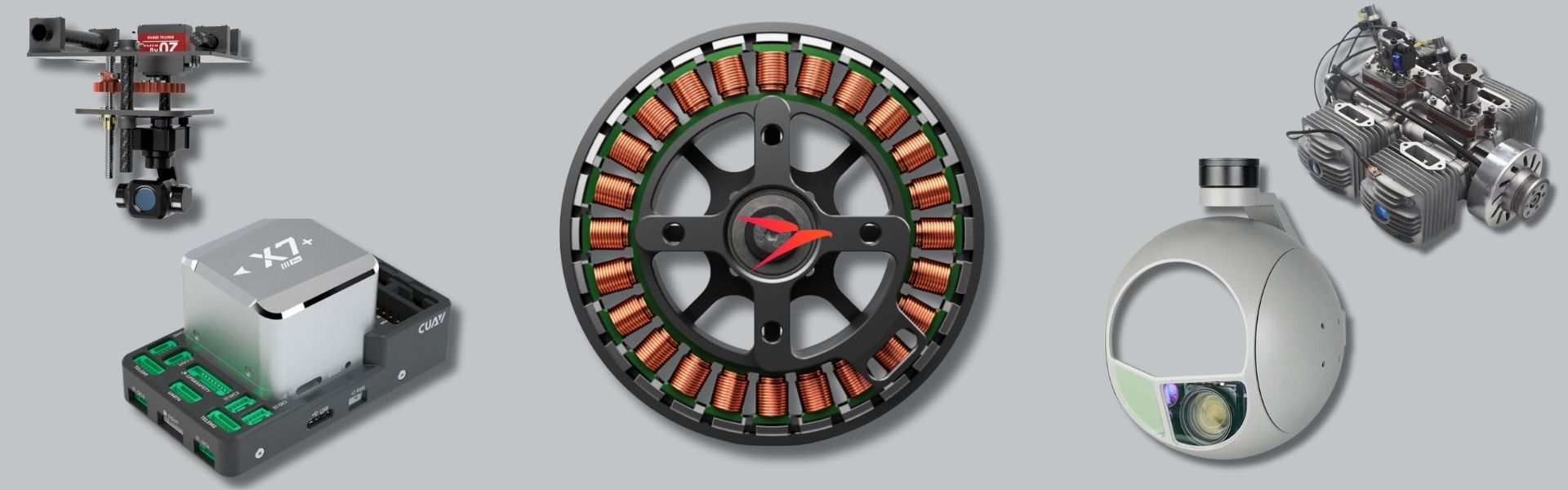
The Holybro Pixhawk Jetson Baseboard is based on the Pixhawk Autopilot Bus open source specification and the NVIDIA Jetson Orin NX/Nano Carrier Board. The Pixhawk Autopilot Bus (PAB) Form Factor enables this to be used with any PAB flight controller such as the Pixhawk 6X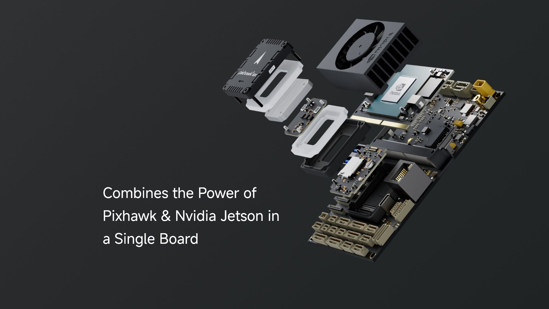


Pixhawk 6X (ICM-45686)
Processors & Sensors
- FMU Processor: STM32H753
- 32 Bit Arm® Cortex®-M7, 480MHz, 2MB flash memory, 1MB RAM
- IO Processor: STM32F103
- 32 Bit Arm® Cortex®-M3, 72MHz, 64KB SRAM
- On-board sensors (Shipping Currently, Rev8)
- Accel/Gyro: 3x ICM-45686 (with BalancedGyro™ Technology)
- Barometer: ICP20100 & BMP388
- Mag: BMM150
Baseboard Port & Connection
Jetson Connectors
- 2x Gigabit Ethernet port
- Connected to both Jetson & Autopilot via Ethernet switch (RTL8367S)
- Ethernet Switch powered by circuit as the Pixhawk
- 8-pin JST-GH
- RJ45
- Connected to both Jetson & Autopilot via Ethernet switch (RTL8367S)
- 2x MIPI CSI Camera Inputs
- 4 Lanes each
- 22-Pin Raspberry Pi Cam FFC
- 2x USB 3.0 Host Port
- USB A
- 5A Current Limit
- 2x USB 2.0 Host Port
- 5-Pin JST-GH
- 0A Current Limit
- USB 2.0 for Programming/debugging
- USB-C
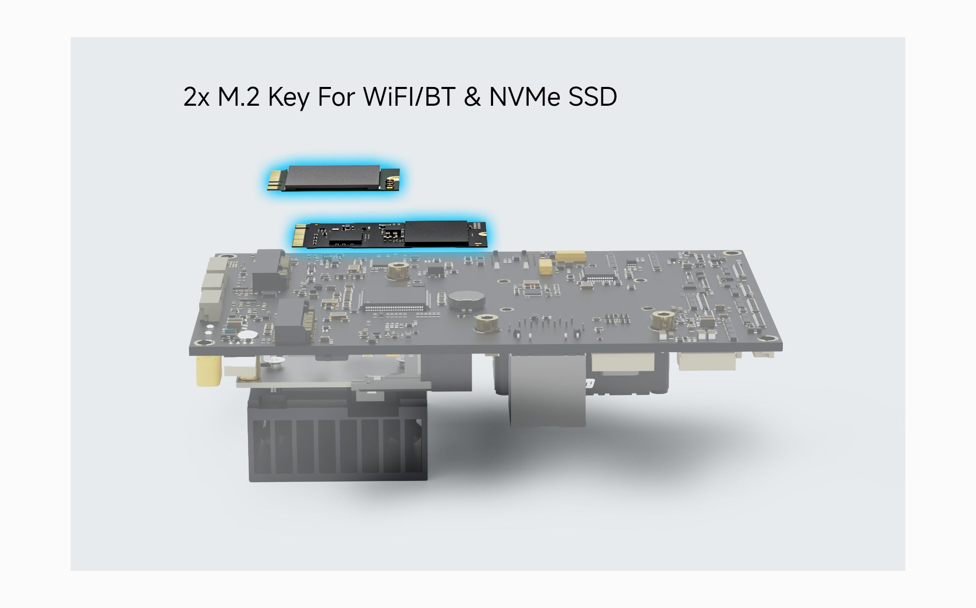
- 2 Key M 2242 for NVMe SSD
- PCIEx4
- 2 Key E 2230 for WiFi/BT
- PCIEx2
- USB
- UART
- I2S
- Mini HDMI Out
- 4x GPIO
- 6-pin JST-GH
- CAN Port
- Connected to Autopilot’s CAN2 (4 Pin JST-GH)
- SPI Port
- 7-Pin JST-GH
- I2C Port
- 4-Pin JST-GH
- I2S Port
- 7-Pin JST-GH
- 2x UART Port
- 1 for debug
- 1 connected to Autopilot’s telem2
- Fan Power Port
- IIM42652 IMU
- Input Power
- XT30 Connector
- Voltage Rating: 7-21V (3S-4S)
- Separate input power circuits than the Autopilot to ensure flight safety
- Holybro UBEC 12A (3-14S) can be used for application above 4S
- Note: The Pixhawk Jetson Baseboard onboard BEC is only rated for 7-21V (3S-4S). Using the external "UBEC 12A (3-14S)" can provides redundancy and easier replacement in case of BEC failure.
- Power Requirements
- 8V/3A Minimum
- Depends on Usage and Peripherals
Autopilot Connectors
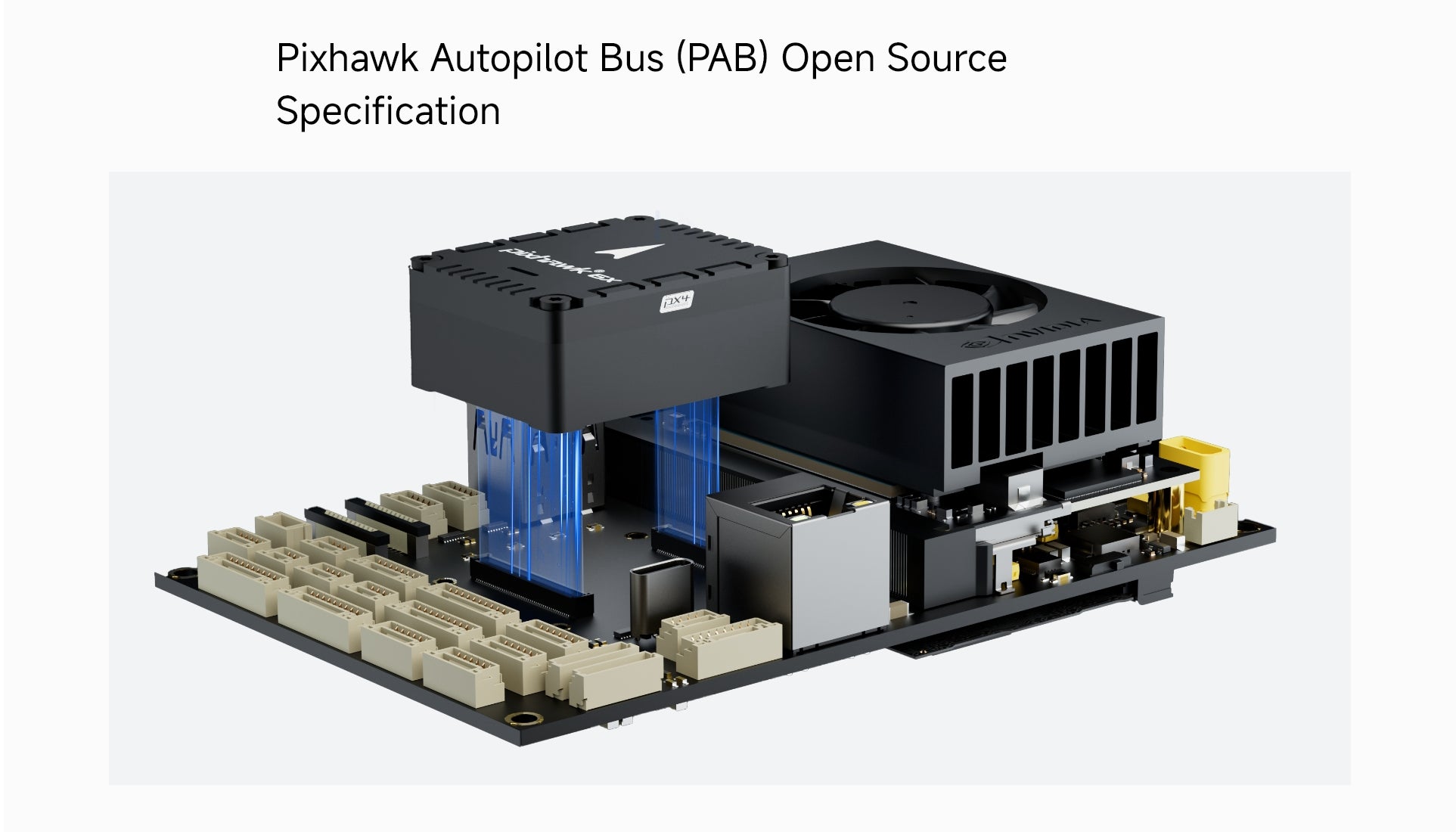
- Pixhawk Autopilot Bus Interface
- 100 Pin Hirose DF40
- 50 Pin Hirose DF40
- Redundant Digital Power Module Inputs
- I2C Power Monitor Support
- 2x – 6 Pin Molex CLIK-Mate
- Power Path Selector w/ Overvoltage Protection
- Voltage Ratings:
- Max input voltage: 6V
- USB Power Input: 4.75~5.25V
- Full GPS Plus Safety Switch Port
- 10-Pin JST-GH
- Secondary (GPS2) Port
- 6-pin JST-GH
- 2x CAN Ports
- 4 Pin JST-GH
- 3x Telemetry Ports with Flow Control
- 2x 6-Pin JST-GH
- 1 is connected to Jetson’s UART1 Port
- 16 PWM Outputs
- 2x 10-Pin JST-GH
- UART4 & I2C Port
- 6-Pin JST-GH
- 2x Gigabit Ethernet port
- Connected to both Jetson & Autopilot via Ethernet switch (RTL8367S)
- 8-pin JST-GH
- RJ45
- AD & IO
- 8-Pin JST-GH
- USB 2.0
- USB-C
- 4-pin JST-GH
- DSM Input
- 3-pin JST-ZH 1.5mm Pitch
- RC in
- PPM/SBUS
- 5-pin JST-GH
- SPI Port
- External Sensor Bus (SPI5
- 11-Pin JST-GH
- 2x Debug Port
- 1 for FMU
- 1 for IO
- 10-Pin JST-SH
- Dimensions (Without Jetson and Flight Controller Module)
- 126x80x38mm
- Weight
- With Jetson, Heatsink, Flight Controller, M.2 SSD, M.2 Wi-Fi Module 203.2g
UBEC-12A Specifications
- Input voltage: 3~14S (XT30)
- Output voltage: 6.0V/7.2V/8.0V/9.2V (recommend 7.2V if supplying power to Jetson Board)
- Output Current
- Continuous: 12A
- Burst: 24A
- Size: 48x33.6x16.3 mm
- Weight: 47.8g
Reference Wiring Diagram


0
Total items
Dhs. 0.00
Taxes, discounts and shipping calculated at checkout.
Product subtotal
Build your Project with us